From 2D Plans to 3D Models: How AI Construction Extraction Is Changing the Game
Every construction project starts with drawings. Floor plans, structural grids, MEP layouts, civil site plans, signage packages — stacks of sheets that encode the entire intent of a building. For decades, the path from those flat drawings to a buildable understanding of the project has been manual: estimators count symbols, model builders trace geometry, and project managers cross-reference schedules by hand.
That is changing. AI-powered extraction now reads 2D construction drawings end to end — classifying sheet types, detecting every component, parsing schedules, and producing structured takeoffs in minutes. And the latest capability goes further: it reconstructs a full 3D model from those same 2D plans, letting you walk through a building before a single piece of steel is erected.
This post walks through the entire pipeline — from PDF upload to interactive 3D walkthrough — and explains why it matters for general contractors, MEP subcontractors, civil engineers, and architects.
The Problem: Drawings Are Rich, but Extraction Is Painful
A typical commercial construction project has 50 to 500 sheets. Each sheet contains hundreds of components: structural columns, beams, walls, ductwork, conduit runs, light fixtures, sprinkler heads, signage, parking layouts, and more.
Estimators and preconstruction teams currently spend 40 to 60 percent of their bid preparation time just on takeoffs — identifying, counting, and measuring components from those drawings. The process is repetitive, error-prone, and does not scale. Miss a few sheets or miscount a symbol and you lose margin. Spend too long and you lose the bid entirely.
The problem is not a lack of information. The drawings contain everything needed to build. The problem is that information is locked inside flat geometry, symbols, and text annotations that were designed for human eyes, not software pipelines.
Step 1: AI-Powered Drawing Classification
The extraction pipeline begins the moment a PDF drawing set lands in the system. Before a single component is counted, the AI needs to understand what it is looking at.
Automatic sheet classification identifies each page as one of dozens of drawing types:
- Structural plans — foundation, framing, column layouts, beam schedules
- MEP layouts — electrical one-line diagrams, mechanical duct plans, plumbing risers
- Architectural plans — floor plans, reflected ceiling plans, wall sections
- Civil site plans — grading, utility routing, parking layouts, landscape
- Interior plans — finish schedules, furniture layouts, partition types
- Signage packages — sign schedules, sign count totals, detail sheets, location plans
- Schedules and legends — door schedules, fixture schedules, panel schedules
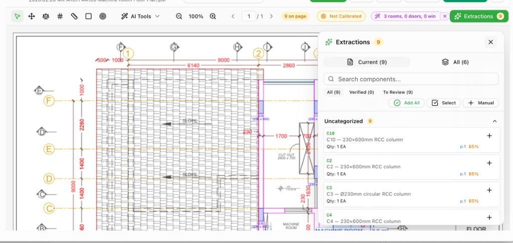
The classifier uses a combination of regex-based pattern matching and vision-language models to score each page. For a signage package, for example, the system identifies which pages are schedules (the source of truth for quantities), which are sign count totals (the reconciliation target), and which are detail sheets (metadata only, not for counting).
This classification step is critical. Without it, the extraction engine would treat a signage fabrication detail the same as a sign schedule, pulling material callouts and structural tags into the takeoff as if they were countable items.
Step 2: Component Extraction Across Every Discipline
Once sheets are classified, the extraction engine processes each page type with discipline-specific intelligence.
Structural Extraction
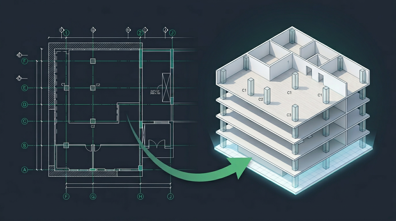
The AI identifies columns (C1, C2, C3), beams, slabs, footings, shear walls, and bracing from structural plans. It reads the column schedule for sizes and reinforcement, cross-references grid lines for placement, and outputs every structural element with its type, size, location, and quantity.
MEP Extraction
For electrical drawings, the system detects every receptacle, switch, light fixture, panel, conduit run, and wire home run. For mechanical, it reads duct layouts, diffusers, VAV boxes, and equipment schedules. For plumbing, it identifies fixtures, pipe runs, and risers.
Each extracted item includes a type code, description, quantity, unit, and confidence score. The AI does not just count — it understands context. A "2P" annotation next to a receptacle means it is a duplex, not that there are two separate items.
Civil and Site Extraction
Civil site plans get their own extraction logic. The system identifies parking stalls, curb cuts, catch basins, manholes, utility lines, retaining walls, and grading annotations. It reads civil legend tables and cross-references them with plan annotations.
Architectural and Interior Extraction
Architectural drawings yield walls, doors, windows, room boundaries, ceiling types, and finish annotations. The AI reads door and window schedules, maps them to plan symbols, and produces a complete architectural takeoff.
Interior plans add furniture, millwork, partition types, and finish schedules to the extraction.
Signage and Wayfinding Extraction
Signage packages require a unique approach. The AI identifies sign type codes (A, B, C1, 12A, 17B) from sign schedules, maps them to descriptions and quantities, and hard-blocks false positives like material callouts (M8, P1, V2), structural tags (HSS4, WT8), and architectural background items (bollards, EV chargers, drains).
The system then reconciles extracted totals against the package's own sign count total page — the single best validation step for signage accuracy.
Step 3: From Flat Extraction to 3D Reconstruction
Here is where the pipeline becomes transformative.
Traditional takeoff software stops after extraction. You get a spreadsheet — a bill of materials with counts and descriptions. That is useful for estimating, but it does not give you spatial understanding. You cannot see how the building fits together, where clashes might occur, or whether the design intent translates to buildable reality.
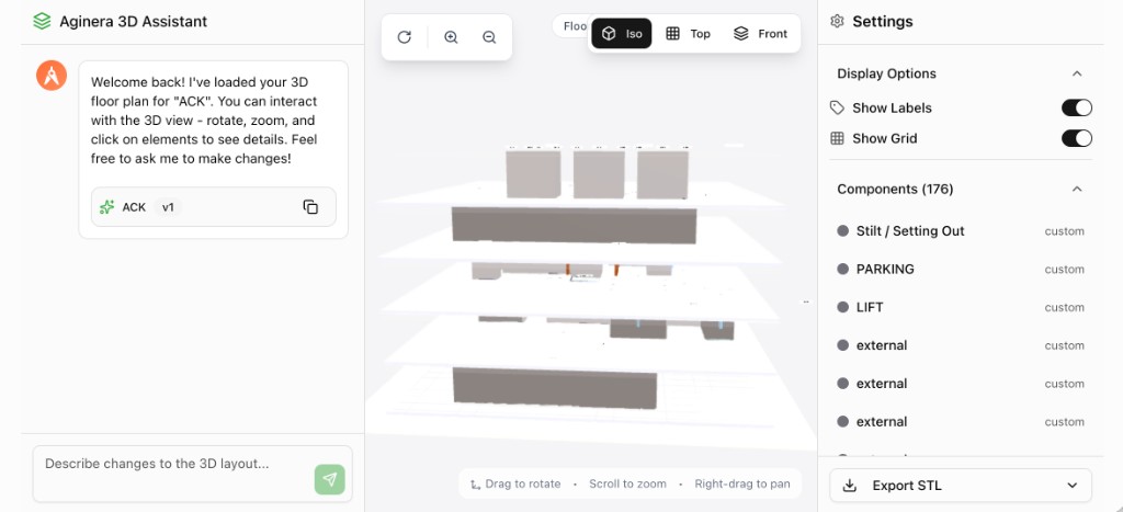
Aginera's 3D assistant takes the extracted components and reconstructs them into an interactive 3D model.
Try it yourself: Our free AI Floor Plan to 3D converter lets you upload any floor plan PDF and see the 3D model instantly — no signup required. The same technology described in this article powers the tool.
How It Works
-
Wall and room detection — The AI interprets wall lines, partitions, and room boundaries from the floor plan. It determines wall thickness, height, and material from schedule annotations.
-
Structural element placement — Columns, beams, and slabs are positioned in 3D space using grid coordinates extracted from the structural plan. The system reads column schedules for dimensions and maps each element to its grid intersection.
-
Component positioning — Extracted components — lifts, stairs, parking areas, mechanical equipment, light fixtures — are placed at their plan coordinates and extruded or modeled in 3D.
-
Multi-level assembly — When the drawing set includes multiple floors, the system stacks levels automatically, aligning grid lines and vertical elements across stories.
-
Interactive rendering — The resulting model loads in a browser-based 3D viewer powered by Three.js. You can orbit, zoom, pan, click individual elements to inspect details, and switch between isometric, top-down, and front elevation views.
Chat-Based Editing
The 3D assistant is not just a viewer — it is an interactive agent. You can describe changes in natural language:
- "Move the lift core 2 meters to the east"
- "Add a column at grid intersection D-4"
- "Change the ceiling height on level 2 to 3.5 meters"
- "Highlight all fire-rated walls"
The assistant interprets the instruction, modifies the 3D model, and shows the result immediately. This turns 3D review from a passive viewing exercise into an active design conversation.
Why This Matters for Construction Teams
For General Contractors
You get a 3D understanding of the project during preconstruction — before BIM coordination, before trade buyout. This lets you identify scope gaps, validate subcontractor bids against the actual design, and communicate project complexity to owners and stakeholders.
For MEP Subcontractors
Extraction gives you accurate quantities in minutes instead of days. The 3D model lets you verify spatial relationships — will this duct run fit below that beam? Does the conduit routing conflict with the mechanical layout? These questions, previously answered during construction with expensive field changes, can now be flagged during estimation.
For Civil Engineers
Site plan extraction automates the tedious counting of parking stalls, manholes, catch basins, and utility connections. The 3D view shows grading relationships and site layout in a way that flat plans cannot.
For Architects
The 3D reconstruction provides instant visual validation of floor plans. You can verify that room proportions, circulation paths, and structural placements match design intent — without waiting for a full BIM model to be built.
For Signage Contractors
Signage takeoffs are notoriously error-prone because of the mix of schedules, detail sheets, and material specs in a single package. AI extraction with reconciliation against the sign count total eliminates the most common source of errors: confusing material callouts with countable items.
The Business Impact
The numbers are straightforward:
- 80% reduction in takeoff time — A 200-sheet drawing set that took 3 days to take off manually now completes in 30 minutes.
- 95%+ extraction accuracy — Validated against schedule-page totals and reconciled across sheets.
- Zero missed sheets — The AI processes every page. No accidental skips, no forgotten addenda.
- Instant 3D visualization — Eliminates the weeks typically needed to build a coordination model from scratch.
- Faster bid turnaround — Respond to ITBs in hours instead of days, increasing your win rate.
What Drawing Types Are Supported
Aginera currently supports extraction and 3D reconstruction across:
| Drawing Type | Extraction | 3D Reconstruction |
|---|---|---|
| Structural Plans | Full | Full |
| Electrical Layouts | Full | Component placement |
| Mechanical Plans | Full | Component placement |
| Plumbing Plans | Full | Component placement |
| Architectural Floor Plans | Full | Full |
| Civil Site Plans | Full | Partial |
| Interior Plans | Full | Full |
| Signage Packages | Full (with reconciliation) | — |
| Schedules & Legends | Parsed as reference | — |
Getting Started
There are two ways to experience this technology:
Quick Start: Free Floor Plan to 3D Tool
Try the free converter — upload any floor plan PDF, and in under 90 seconds the AI detects every room, wall, door, and window, then builds an interactive 3D model. No account required for your first 5 plans. Perfect for architects, interior designers, and anyone who wants to see a floor plan in 3D.
Full Pipeline: Construction Takeoff & Estimation
For complete construction document processing — MEP extraction, cost estimation, BOM generation, and multi-trade takeoff — the full workflow is:
- Upload your PDF drawing set — single file or multi-document package.
- Classify — The AI automatically identifies every sheet type.
- Extract — Components, quantities, and schedules are pulled into a structured takeoff workbook.
- Review — Validate the extraction against the drawing. Flag items for adjustment.
- Generate 3D — One click converts the extraction into an interactive 3D model.
- Collaborate — Share the takeoff and 3D model with your team, trade partners, or client.
Start a free project to experience the full pipeline. Paid plans unlock unlimited extractions, 3D reconstruction, addenda tracking, and team collaboration features.
What Comes Next
We are actively expanding the extraction engine to handle more complex drawing conventions — phased construction, renovation overlay plans, and multi-building campuses. On the 3D side, we are adding MEP routing visualization, clash detection, and direct export to IFC for BIM integration.
The vision is clear: any drawing set, fully understood, instantly visualized. No manual counting, no manual modeling, no lost information between the design and the estimate.
Try the 2D to 3D Pipeline Right Now
Want to see this technology in action? Our free AI Floor Plan to 3D converter lets you upload any floor plan PDF and watch the AI detect rooms, walls, doors, and windows — then build an interactive 3D model you can explore. No signup needed for your first 5 plans.
For a deeper look at how our data-grounded rendering approach differs from generic AI renderers, read our technical breakdown: Floor Plan to 3D: Why Most AI Renderers Get It Wrong.
For full construction takeoff with MEP extraction, cost estimation, and BOM generation, start a free project and upload your drawing set today.