Most of the excitement around AI and CAD is about one step: type a prompt, get a model. That step is real, and it is useful. But it is not where most engineering work starts. Most work starts from a drawing that already exists, often only as a PDF, and the job is to change it: a longer base, a bigger bore, two more holes.
That job is a loop, not a step:
PDF → CAD → 3D model → a change in plain words → PDF again.
This post walks that loop on one real part, run on production, with the numbers the product reported. It also says what the loop does not do.
The short answer
You cannot usefully edit a PDF drawing with AI by changing the PDF. What works is going round: convert the PDF to CAD, build a 3D solid from the drawing's dimensions, change the solid by typing, and draw the changed solid back onto a new dimensioned sheet. Aginera does all four in one place, shows the original and the changed version side by side, and gives you the edited STEP file and a new drawing PDF.
Why the loop matters more than the prompt
A model made from a prompt has no history. A drawing has plenty: someone made it, a shop built from it, and a customer approved it. When that part changes, three things are needed that a text-to-model step does not give you:
- The existing part as a starting point, not a fresh guess at it.
- A change that touches only what was asked. If the base gets longer, the bore must not move.
- A record of the change that a person can check: what was added, what was removed, and the drawing that goes with it.
When we looked at what is available, we found tools for each piece: PDF to 3D, text to model, text edits, and drawings from a 3D model. We did not find one that chains them from a PDF you already have back to a PDF you can issue. That is the gap this loop closes.
The worked example: a pillow block bracket
The part is a welded pillow block bracket: a base plate, an upright with an arched top and a bore, and two gussets. The only thing we had was a one-page PDF with three views and dimensions.
Step 1: PDF to CAD
Upload the PDF in PDF to CAD. The drawing is traced into an editable CAD file, with outlines, hidden lines, centre lines, dimensions and text on their own layers. This part is free to convert and view.
Step 2: the 3D model
Because the sheet is a dimensioned part, the 3D model is built without a click, from the numbers on the drawing. It was ready in under a minute: 200 × 120 × 160 mm, the size the drawing gives.
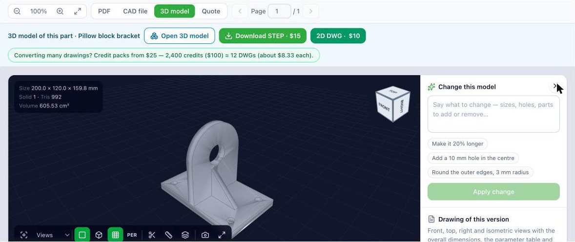
Under the viewer, the page says what had to be assumed. Here it was one thing: the plate thickness, taken from the material note. That line matters. A model that hides its guesses is worse than no model.
Step 3: change it by typing
In the box beside the model, we typed:
Make the base plate 240 mm long instead of 200 and open the bore to 50 mm
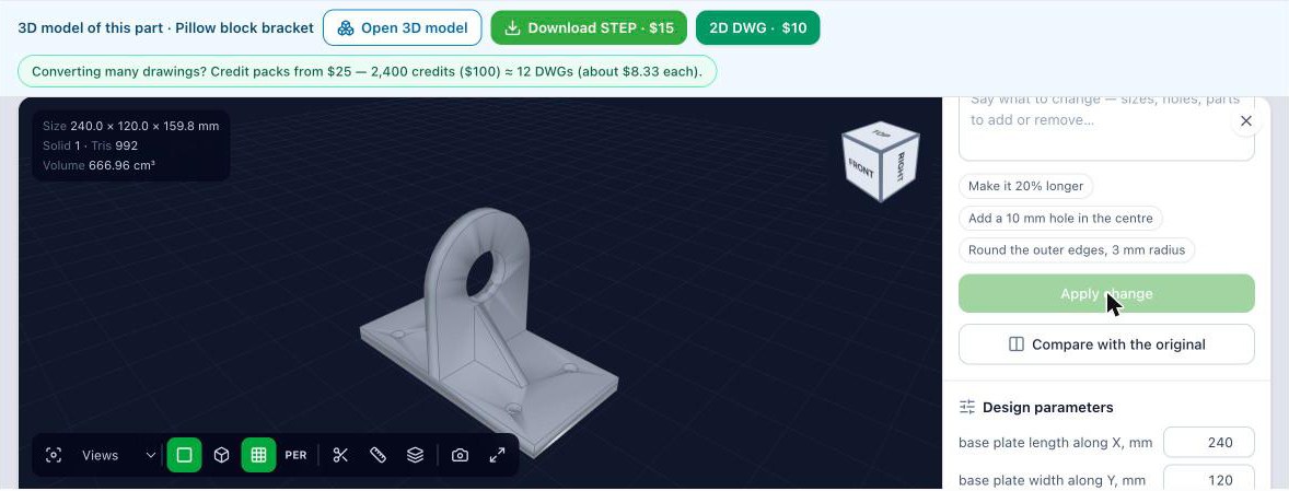
About half a minute later the model was rebuilt at 240 × 120 × 160 mm. The gussets, the upright and the mounting-hole pattern were left alone, except where the longer base moved the holes with it.
Two details make this more than a regenerate button:
- Every change is a revision. The original is never overwritten, and one click undoes the last change.
- The model has named design parameters. Base length, bore diameter, hole diameter, gusset size. You can edit a number directly and rebuild, with no AI involved.
Step 4: see exactly what changed
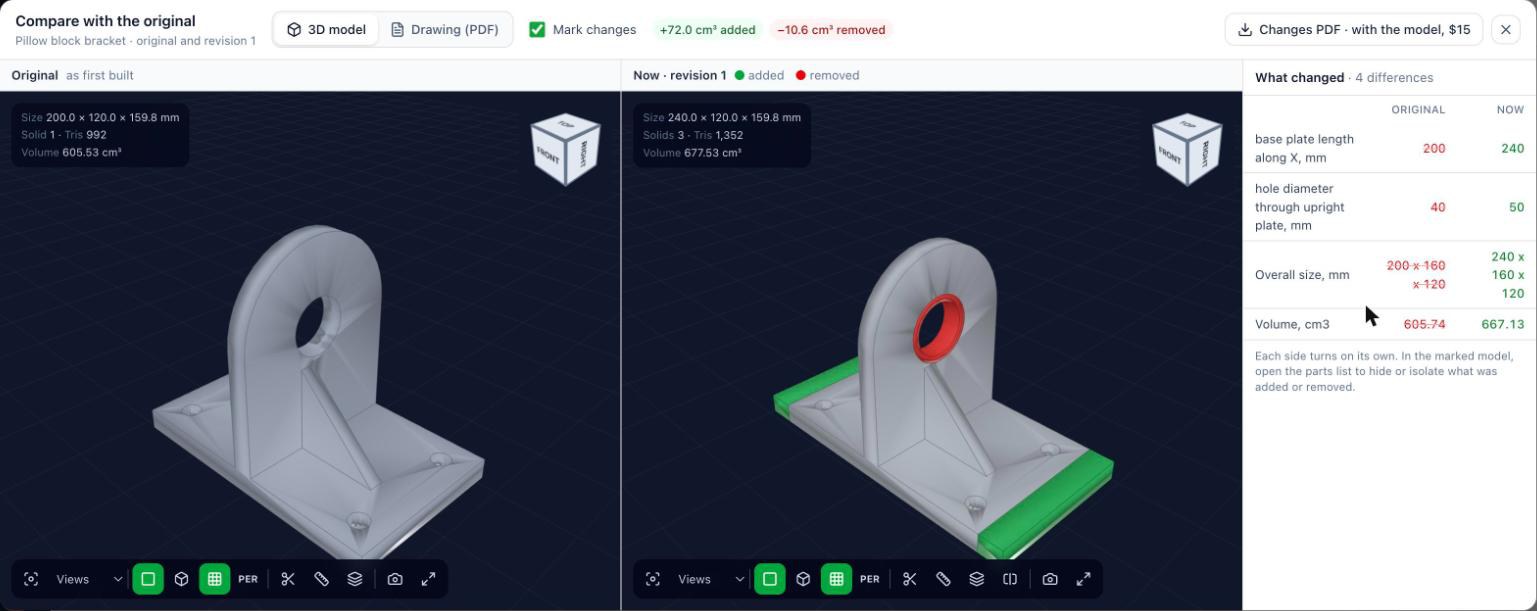
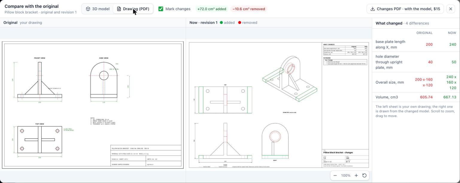
Compare with the original opens a split screen. On the left is the original; on the right, the changed model with added material in green and removed material in red.
The numbers for this change:
| Original | Now | |
|---|---|---|
| Base plate length | 200 mm | 240 mm |
| Bore diameter | 40 mm | 50 mm |
| Overall size | 200 × 160 × 120 mm | 240 × 160 × 120 mm |
| Volume | 605.74 cm³ | 667.13 cm³ |
| Material added | 72.0 cm³ | |
| Material removed | 10.6 cm³ |
The added and removed volumes are not estimates from the text of the change. They come from cutting one solid against the other. They also check themselves: 72.0 added minus 10.6 removed is the 61.4 cm³ the volume went up by.
Step 5: back to PDF
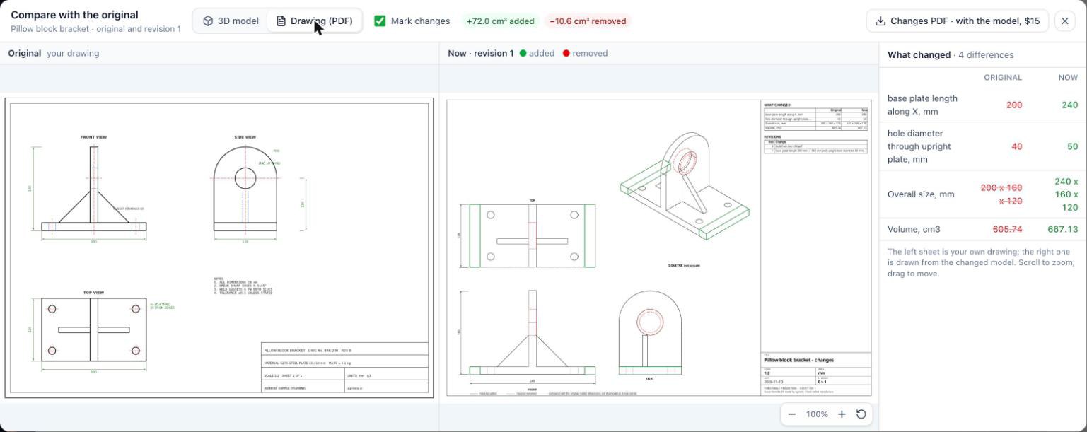
The same compare view has a drawing tab. On the left is the PDF we started from. On the right is a new sheet, drawn from the changed model, with the added edges in green and the removed edges in dashed red.
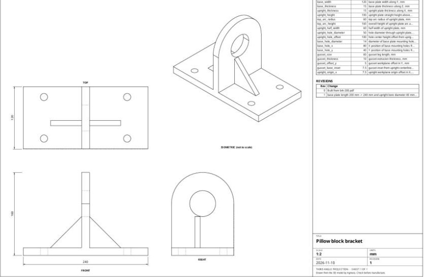
The clean sheet, without the marks, is the new drawing: front, top, right and isometric views, the overall dimensions, a table of the design parameters, and the list of revisions in the words that were typed.
That is the loop closed. A PDF went in; a STEP file, a marked-up comparison and a new PDF came out.
Three things under the hood that make it trustworthy
The part is a program, not a picture. The model is stored as a short parametric program that the CAD kernel builds into an exact solid. A change edits that program. That is why the output is a STEP file with real faces and edges, not a mesh, and why a change can leave everything else alone.
Dimensions on the new drawing are measured, not written. The overall dimensions on the sheet are read from the solid after it is built. A drawing that says 240 is 240 in the model.
Parameters are added only when nothing moves. A model built from a drawing starts with bare numbers. To give it named parameters, the program is rewritten, then rebuilt and compared with the original piece by piece: volume, surface area, centre of mass and bounding corners must all match. If anything differs, the rewrite is thrown away. On ten real customer models, nine rewrites passed that check and one was left as it was. We would rather have no parameters than wrong ones.
The same loop, starting from a sentence
If there is no drawing yet, the loop starts from text instead. In Text to CAD we typed a hydraulic cylinder with a 63 mm bore, a 250 mm stroke and a 28 mm rod, as five separate parts. It came back as a five-part assembly, 326 mm long. One typed change, a 400 mm stroke and a 36 mm rod, made it 476 mm long, and the compare view listed stroke 250 → 400 and rod 28 → 36.
Everything after the first model is the same: change, compare, drawing.
What it does not do
- It does not carry over everything on your drawing. Tolerances, surface finish, weld symbols, notes and your title block stay on the original. The new sheet has its own title block.
- Feature dimensions are in a table, not on leaders. The views carry the overall dimensions. Hole diameters, thicknesses and counts are in the design-parameter table.
- It is for regular parts. Plates, brackets, flanges, frames, enclosures, shafts, simple assemblies. Not organic shapes, and not buildings.
- It is a first model, not a release. Some assumptions are always made, and they are listed. Check before you manufacture.
- Very large assemblies are slower and rougher. A five-part assembly took about a minute. A machine with dozens of parts will lose detail.
Try it
- Have a drawing? Start at PDF to CAD and open the 3D model tab.
- No drawing yet? Start at Text to CAD.
- The step-by-step guide is in the docs: Change a model and compare.
Creating, viewing, changing and comparing are free with an account. The STEP file, the drawing PDF and the changes PDF are a one-time $15 per model.


