Change a model and compare
Change a 3D model by typing or by editing its design parameters, compare it with the original in a split screen, and download the edited STEP file and a new dimensioned drawing.
Purpose
Edit a 3D model without a CAD program, see exactly what changed, and get the edited files. It works on any model Aginera built: from a PDF drawing or from a description.
Who this is for
- Fabricators and engineers revising a part: a longer base, a larger bore, more bolt holes.
- Anyone who needs a new drawing of a part after a change.
Prerequisites
- A 3D model in the 3D model tab of PDF to CAD, or in Text to CAD.
Change by text
-
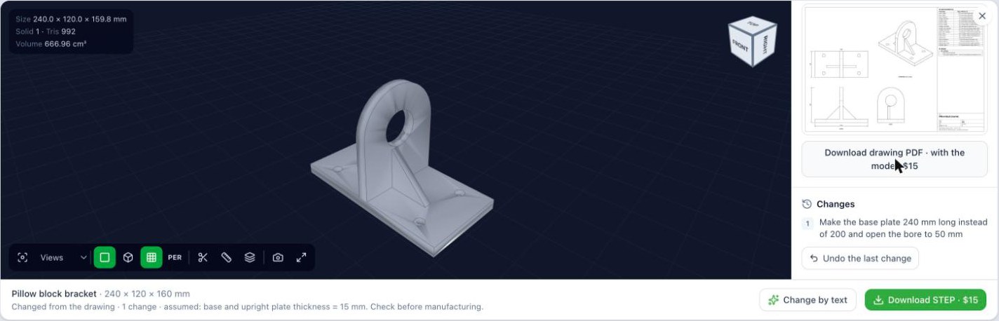
In Change this model, type what to change, for example
Make the base plate 240 mm long instead of 200 and open the bore to 50 mm. -
Select Apply change. The button reads Rebuilding the model… while the solid is rebuilt.
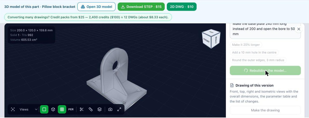
-
The viewer shows the changed model and its new size. Only what you asked for changes; everything else stays as it was.
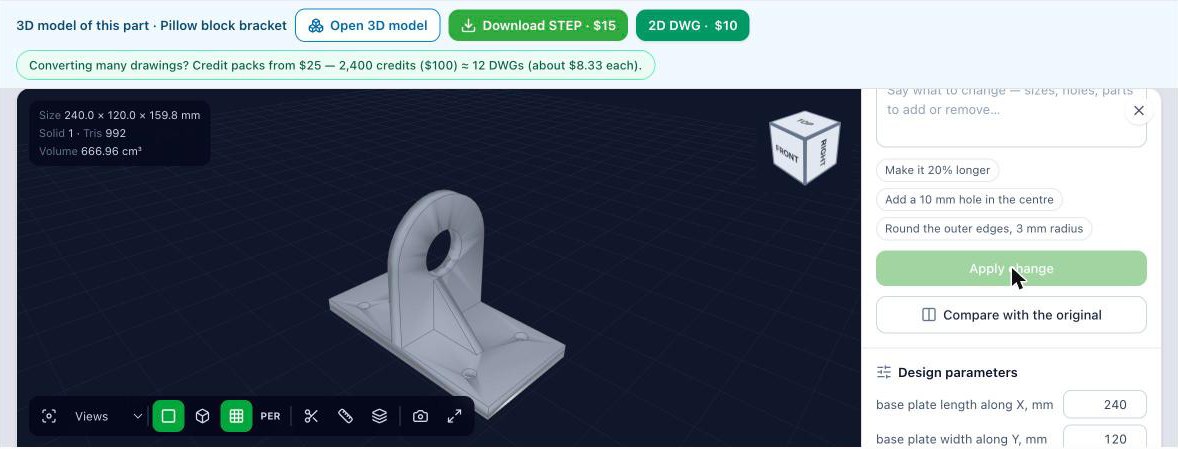
Say one thing at a time for the cleanest result: sizes, holes, a part to add, or a part to remove. If a change cannot be made to this model, a message says why and the model stays as it was.
Change a value
Every model lists its Design parameters: the lengths, diameters, and counts that drive it.
- Type a new number next to a parameter. Changed values are highlighted.
- Select Rebuild with 1 new value (or the number you changed). Reset puts the typed values back.
Changing a value uses no AI and is always free.
Models built from a drawing
A model built from a PDF drawing gets its design parameters a few seconds after you first open it. Until then the list may be empty; changing by text works straight away.
Undo
Every change is a new revision, listed under Changes. Select Undo the last change to go back one revision. The original is always kept.
Compare with the original
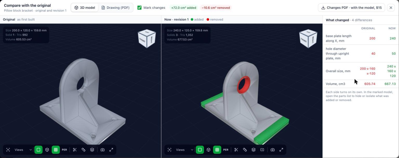
Select Compare with the original. A split screen opens with the original on the left and the model as it now stands on the right.
-
3D model tab: two viewers. With Mark changes on, the right side shows material that was added in green and material that was removed in red.
-
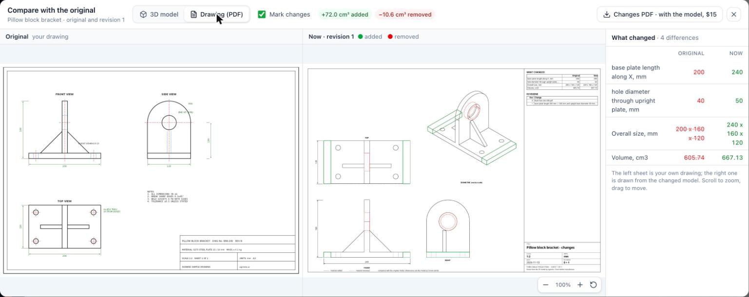
Drawing (PDF) tab: two sheets. For a model built from your PDF, the left sheet is your own drawing and the right sheet is drawn from the changed model, with added edges green and removed edges dashed red. Scroll to zoom, drag to move.
-
What changed: every difference as original → now, with the overall size and volume, and the volume added and removed at the top.
Select Changes PDF to download the marked-up sheet.
Get the new drawing
-
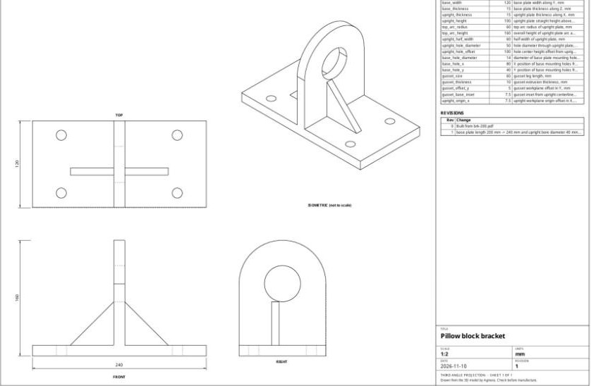
Under Drawing of this version, select Make the drawing. A preview appears in the panel; select it to enlarge.
-
The sheet shows front, top, right, and isometric views, the overall dimensions measured from the solid, the design-parameter table, and the list of revisions.
-
Select Download drawing PDF for the PDF, and Download STEP for the model. Both are always of the model as it now stands, so after a change you download the edited version.
Expected result
- The changed model in the viewer, with its revisions listed under Changes.
- A comparison you can show a customer: what was added, what was removed, and every value that changed.
- An edited STEP file, a new drawing PDF, and a changes PDF.
Troubleshooting
- "That change cannot be made to this model": the instruction was unclear or asked for something that is not a change to this part. Say the size, feature, or position you want.
- "The changed model could not be built": say the change another way, or in smaller steps.
- A parameter value will not rebuild: the value makes the part impossible (a hole wider than the plate, for example). Try a value closer to the current one.
- "You have used today's free 3D changes": free accounts have a daily number of AI changes. Editing a value is always free, and buying the model lifts the limit for it.
- Overall dimensions only: the drawing dimensions the overall size on the views. Feature sizes such as hole diameters are listed in the design-parameter table.