Text to CAD: describe a part, get a 3D model
Type what you need with its main sizes. Aginera builds a real solid — a STEP file, not a mesh — that you can turn, change by typing, and get back as a dimensioned drawing.
Free with an account: create, view and change your model. The STEP file and drawing PDF are a one-time purchase per model.
What is text to CAD?
Text to CAD turns a written description of a part into a 3D CAD model. With Aginera you type what the part is and its main sizes, and get a real solid as a STEP file in under a minute. You then change it by typing, compare the changed model with the original side by side, and download a dimensioned drawing PDF of it. You can also start from a PDF drawing instead of a description.
| What goes in | A typed description with the main sizes (mm or inches), or a PDF part drawing through PDF to CAD |
|---|---|
| What comes out | A 3D solid: STEP file, with each part of an assembly as its own named body |
| How long it takes | Under a minute for a model; about half a minute for a change |
| How you edit it | Type the change, or edit a design parameter value. Every change is a revision you can undo |
| Seeing what changed | Split screen, original beside current: added material green, removed red, every value original and now |
| Back to paper | A dimensioned drawing PDF of any revision: front, top, right and isometric views, parameter table, revision list |
| Price | Free to create, view, change and compare. STEP, drawing PDF and changes PDF: $15 once per model |
| Not for | Free-form or organic shapes, buildings and floor plans, signed-off manufacturing drawings |
Updated November 2026 · Step-by-step guide in the docs
From words to a STEP file in four steps
Describe it
What the part is and its main sizes, in millimetres or inches. Separate parts of an assembly are built as separate bodies.
Turn it and check it
The solid opens in the 3D viewer in under a minute: rotate, section, measure, explode the parts.
Change it by typing
Say what to change, or edit a design parameter. Each change is a revision you can undo.
Take it out
Download the edited STEP file for your CAD program and a dimensioned drawing PDF of the same revision.
Change the model, get a new drawing
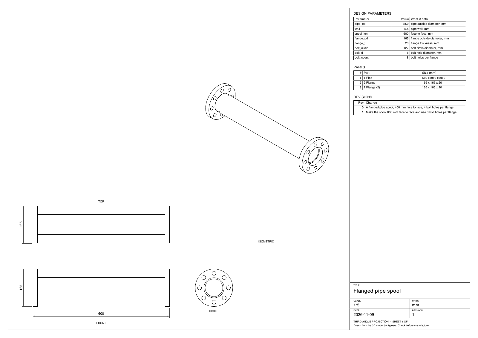
This pipe spool was 400 mm long with four bolt holes per flange. One typed change — “Make the spool 600 mm face to face and use 8 bolt holes per flange” — rebuilt the solid, and the sheet on the right was drawn from the new revision.
- • Overall dimensions are measured from the solid, so they are always the model's true size.
- • The design-parameter table lists every size and count that drives the part.
- • The revision table records each change in your own words.
Already have a drawing? PDF to CAD builds the 3D model from your PDF, and the same change-by-text and new-drawing tools work on it.
See exactly what changed
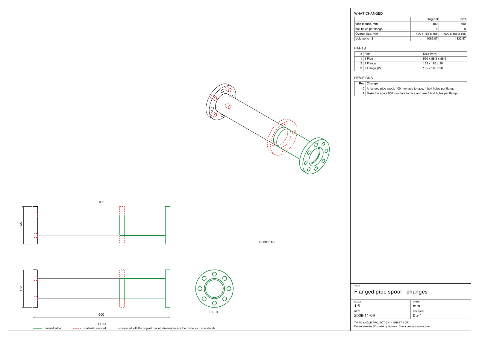
Compare opens the original and the changed model side by side — as 3D models you can turn, or as drawings that zoom and pan together.
- • Green is material that was added; red is material that was removed.
- • Every parameter, the overall size and the volume are listed as original and now.
- • The marked-up sheet downloads as a PDF, next to the edited STEP file and drawing.
The full loop
PDF to CAD, edit by text, back to PDF
A drawing that only exists as a PDF can go all the way round: converted to CAD, rebuilt as a 3D model, changed in plain words, and drawn back onto a new sheet.
- Step 1
PDF
Upload the part drawing in PDF to CAD.
- Step 2
CAD + 3D
An editable CAD file, and a 3D solid built from the dimensions.
- Step 3
Change by text
"Make the base 240 mm long and open the bore to 50 mm."
- Step 4
PDF again
A new dimensioned drawing of the changed model, and the STEP file.
Read the worked example: From PDF to CAD and back to PDF: editing a part drawing by typing · or start with PDF to CAD.
Frequently asked questions
What is text to CAD?
You describe a part in plain words — what it is and its main sizes — and software builds the 3D CAD model for you. Aginera writes the part as a parametric program and builds it into a real solid, so the result is a STEP file with exact faces and edges, not a triangle mesh.
What can I describe?
Mechanical parts and simple assemblies made of regular shapes: plates, brackets, flanges, enclosures, frames, shafts, spacers, housings, benches, cylinders. Give the sizes you care about; anything you leave out is chosen for you and listed so you can change it. Free-form shapes such as figurines, organic surfaces and buildings are not what it is for.
How do I change the model?
Type the change — "make the wall 3 mm", "add four M6 holes on a 60 mm circle", "remove the lid" — and the model is rebuilt with only that change. Every model also lists its design parameters (lengths, diameters, counts) as numbers you can edit directly. Each change is a new revision and you can undo it.
Can I download the CAD file and the PDF after I edit the model?
Yes. The STEP file and the drawing PDF are always of the model as it now stands, so after an edit you download the edited version. The original is kept as revision 0 and you can go back to it at any time.
Can I see what changed?
Yes. Compare opens a split screen with the original on the left and the changed model on the right, as 3D models or as drawings. Material that was added is marked green and material that was removed red, and a table lists every value as original and now. The marked-up comparison sheet downloads as a PDF.
Can I start from a PDF drawing instead of a description?
Yes. Upload the PDF in PDF to CAD: Aginera converts it to an editable CAD file and, for a dimensioned part or frame drawing, builds the 3D model from its dimensions. The same change-by-text, compare and drawing tools then work on that model, so a drawing goes PDF to CAD, is edited in words, and comes back out as a new PDF.
How is this different from other text-to-CAD tools?
Most text-to-CAD tools stop at the first model. Aginera also takes an existing PDF drawing as the starting point, keeps every change as a revision, shows the original and the changed model side by side with added and removed material marked, and draws the changed model back onto a dimensioned sheet. The output is a STEP solid with named design parameters, not a mesh.
Can I get a drawing from the 3D model?
Yes. Any revision can be turned into a drawing sheet: front, top, right and isometric views with the overall dimensions measured from the solid, the design-parameter table, the parts list of an assembly and the list of changes.
Is it free?
Creating, viewing and changing models is free with an account, with a daily limit on AI changes. The STEP file and the drawing PDF are a one-time purchase per model, which also lifts the limit for that model.
Which CAD programs open the file?
STEP (ISO 10303) opens in SolidWorks, Fusion, Inventor, CATIA, Creo, NX, Onshape and FreeCAD. An assembly keeps each part as its own named body.
How accurate is it?
The sizes you state are used as numbers, not estimated, and the finished solid is checked against its own stated overall size. It is a fast first model, not a signed-off design: check it before you manufacture.