BIM model
Turn extracted devices and traced routes into a routed 3D BIM model — conduit, panels, and circuits reconstructed from a 2D PDF, with engineered vs approved run lengths, no CAD or Revit required.
Purpose
Once symbols are detected and routes are traced, the BIM tab reconstructs them into a routed 3D model — devices placed in space and connected by conduit (or pipe/duct) runs — straight from the 2D PDF. No CAD file, Revit model, or manual modelling required.
Who this is for
Estimators and coordinators who want to see the routed system in 3D — to sanity-check runs, understand the network, and hand a model downstream — without a BIM department.
Open the BIM view
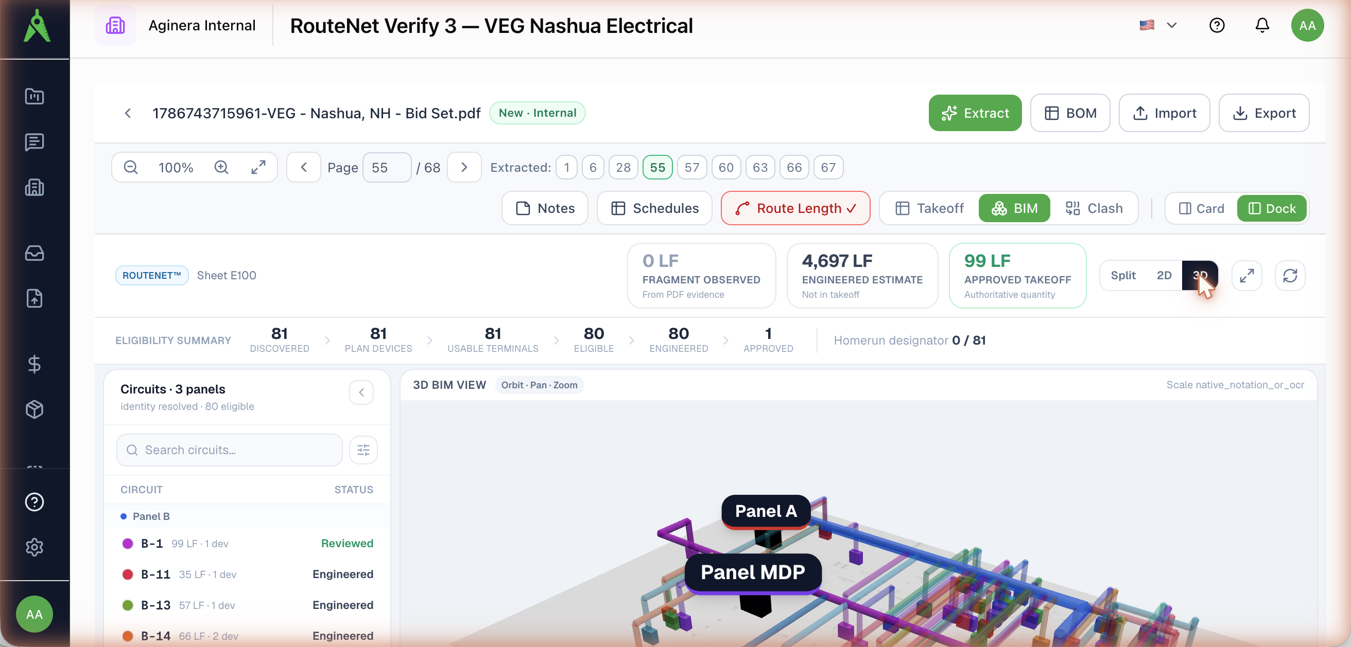
From the takeoff workspace, open the BIM tab. Aginera builds the electrical (or mechanical / plumbing) model and opens a Split view — the 2D plan on one side, the reconstructed 3D BIM view on the other. Toggle Split / 2D / 3D to focus either pane.
What the model tells you
- Run lengths at a glance — Fragment observed (from PDF evidence), Engineered estimate, and the Approved takeoff quantity, so you can see the difference between what's drawn and what you've accepted.
- An eligibility summary — the funnel from Discovered → Plan devices → Usable terminals → Eligible → Engineered → Approved, so every device is accounted for on its way into the model.
- A circuit list — grouped by panel (for electrical), each circuit showing its length, device count, and review status (Engineered, Reviewed). Search or filter to isolate one circuit.
- A routed 3D model — panels and devices placed in space with the conduit runs between them; orbit, pan, and zoom to inspect it.
Reconstructed from 2D
The MEP sheets carry no real elevations, so vertical placement is a display convention — every object exposes its Z evidence in the panel, so you can see how each height was inferred.